Force and Torque on a ladder
Force and Torque on a ladder
About the simulation
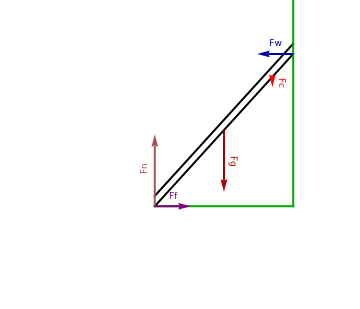
This simulates and displays the forces on a ladder and automatically places the ladder at the smallest angle from the ground that it will be stable at based on choices for the other parameters. The ladder has a moveable paint can that may be placed anywhere on the ladder by adjusting the slider. To avoid clutter, the paint can itself is not shown, just the vector that represents the force it applies to the ladder. The forces are:
◼
Normal Force from Wall (blue vector)
◼
Normal Force from floor (pink vector, labeled: Fn)
◼
Frictional Force from floor (purple vector, labeled: Ff)
◼
Normal Force resulting from gravity on paint can (red vector, labeled: Fc)
◼
Gravity force on ladder center of mass (dark red vector, labeled: Fg)
◼
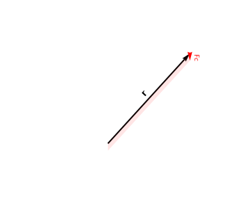
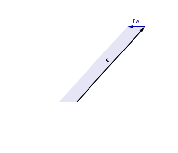
The right part also has a vector r in each of the two diagrams. This represents the position vector that points from the chosen axis of rotation to the point where the force is applied. Essentially this is the in . In In our case, the axis of rotation is taken to be the point where the ladder meets the floor, this is convenient because it eliminates both the torque from the floor’s normal force, and the torque from the frictional force.
r
τ
r
F
◼
If you try to set both the mass of the ladder and the mass of the paint can to 0, the paint can’s mass will be automatically set to 10 to avoid crashing the simulation with a divide by 0 error. For reasons I don’t yet understand, this change is not represented in the slider value for mp. Fortunately, adjusting the slider immediately resolves this.
The second part of the simulation displays two of the force vectors (in their colors) and their position vectors (in black). The area of the parallelogram formed from the cross product is also shown. This area is the torque exerted by the force.
Instructions
1
.First, look at each of the force vectors and ensure that you recall which force each one represents. Now, attempt to determine intuitively what effect increasing the paint can mass would have on the friction force and on the force from the wall. Once you have a guess, try changing the slider labeled “Paint Can’s mass” to verify your intuition.
2
.Now guess what should happen to the minimum angle when the paint can’s location is moved close to the ladder’s base. Once you have a guess, adjust the slider labeled “Location on ladder” to the lowest allowed value.
3
.Ensure that the “Ladder’s mass” is set to 0. What effect should increasing the paint can’s mass have on the minimum angle? What effect will it have on the length of each vector? Once you have a guess, try adjusting the slider and check your answer.
4
.Now look at the 2 vector diagrams on the right side of the simulation. The area of the parallelogram represents the torque from that force. Notice that moving the paint can to the top of the ladder results in a very large torque. How does this contribute to making the minimum ladder angle very large?
5
.Set the friction coefficient as near to 0 as it will go. Notice that the minimum angle approaches 90. Also, notice that, while force vector from the paint can remained large, and the position vector remained large, the torque became nearly 0. This is because the force will no longer cause rotation if it is parallel to the position vector where the force is applied. Since the torque vanishes when the angle is large, we determine that the torque produced by the pain can depends on the cosine of the angle.
6
.Now set the top two sliders all the way down, and the bottom two all the way up. Note that now the force from the wall remains large, as does it’s position vector, but once again, the torque vanishes. Since this torque vanishes when the angle is small, we determine that the torque here depends on the sine of the angle.
6
.1
.Special care should be taken with this technique. If you set the friction coefficient to be near 0, the torque from the wall also vanishes, but only because the force from the wall vanishes. This has nothing to do with the orientation of the vectors, and thus cannot help you choose whether the use of sine or cosine is warranted. Essentially are looking at (equivalently) what the angle needs to be for torque to vanish without the force or position vector vanishing, or when the vectors become parallel.
7
.Use the knowledge that you learned to write out the torque balance equations and determine the maximum angle for some given values of each slider. Then verify that your answer matches the simulation. If it doesn’t, use the simulation to determine where the issue with your equations is and try again.
Out[]=
Out[]=


