Applying Mohr's Circles to Stress States of Continuum
Applying Mohr's Circles to Stress States of Continuum


A Mohr's circle is the representation of the stress state at any point of a continuum in a - plane, where is the normal component of the stress vector on a given material facet and is its tangential component.
σ
τ
σ
τ
Two alternative methods can be used to draw the circle and read its output. The circle is visually the same in both methods although its meaning is different.
This Demonstration helps with understanding the relationship between the two geometric constructions by viewing a synchronous animation in which the stress vector changes with the direction of the normal.
Details
Details
Assume that we know the stress on the facet orthogonal to the direction of the material space and that its scalar components are and .
x
3
σ=
σ
33
τ=
σ
32
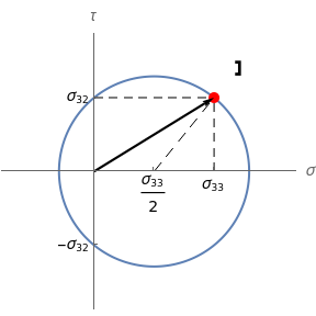
The direct method consists of drawing a circle centered at and passing through the point in the - plane. When the normal to the facet rotates counterclockwise at an angle of , the stress vector on that facet is obtained by joining the origin to the point on the circle at a clockwise arc distance from .
(/2,0)
σ
33
(,)
σ
33
σ
32
σ
τ
θ
2θ
(,)
σ
33
σ
32
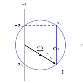
The so-called pole method is carried out by turning the axis in the opposite direction (so that the direct frame is now -) and drawing the circle centered at that passes through the point . This circle is thus visually the same figure as the previous one, but its points belong to a different plane. The point is named the pole of the Mohr's circle. When the normal to the facet rotates counterclockwise at an angle of , the stress vector on that facet is obtained by joining the origin to the point on the circle identified by the cord passing through the pole and parallel to the plane of the facet (i.e., rotated by the same angle and in the same direction from the axis).
τ
τ
σ
(/2,0)
σ
33
(,-)
σ
33
σ
32
P=(,-)
σ
33
σ
32
θ
P
θ
τ
The black arrow represents the stress vector. A symbolic representation of the material facet on which this vector acts is shown close to the stress vector head outside the circle. The construction on the right-hand side is the direct Mohr's circle; the one on the left-hand side is the pole-method circle. The blue segment (parallel to the facet) is the cord identifying the stress vector in the pole method.
More information about the example can be found in[1].
References
References
[1] M. Brocato, Cours de mécanique des structures. Volume 1. Poutres élastiques, Paris: Presses des Ponts, forthcoming.
External Links
External Links
Permanent Citation
Permanent Citation
Maurizio Brocato
"Applying Mohr's Circles to Stress States of Continuum"
http://demonstrations.wolfram.com/ApplyingMohrsCirclesToStressStatesOfContinuum/
Wolfram Demonstrations Project
Published: February 18, 2020