MAM2046W - Second year nonlinear dynamics
Section 2.4: Liénard Systems
In general within mathematics, we often like to be able to make general statements about classes of systems. As an example, one can say that for any dynamical system of the form
x
x
for , given any two solutions and , any linear combination of andwill also be a solution. That’s a general statement about a whole class of problems, and such information can be very useful.
b,c∈R
x
1
x
2
x
1
x
2
It turns out that there is a class of non-linear systems called Liénard Systems, which we can make some bold claims about.
Vector fields of the form:
x
x
equivalent to:
y
x
x
Are known as Liénard Systems, and it turns out that if:
1) are both continuously differentiable functions
fandg
2) function of and is positive for all
gisanodd
x
x>0
3) is an even function of
f
x
4) and finally where:
F(x)=f(u)u
x
∫
0
a) has exactly one zero for positive at
x=a(forpositivea)->F(a)=0
b)
F(x)<0for0<x<a
c)
F(x)>0andF'(x)>=0forx>a
d)
F(x)->∞asx->∞
then the system is guaranteed to have a single stable limit cycle around the origin in the phase plane.
ok, there’s a lot to digest here! First of all let’s look at the vector field itself:
x
x
Writing this as:
x
x
we can see that the acceleration is a function of the velocity and position. This is what we should expect in a two dimensional phase space. Everything is decided by the position and velocity.
If we imagine and we have that , then for positive we have:
f(x)=0
g(x)=-g(-x),andpositiveforpositivex
x
x
and for negative we have
x
x
This is like a spring, where the system is always being accelerated back to the origin.
Now, -zero, we have the situation where there is a force related to the velocity, which is like a damping force, but it’s a position dependent non-linear damping force.
forfnon
What’s all this stuff about the integral formula
ofF?
Well, the statement is that , and . We know that by the definition of the integral. So this says that for and must cross to positive at some point before so that the area below and above the x-axis are the same by the time we get to a. In fact it can cross multiple times before , but again, the area above can never be greater than the area below the axis, and they have to exactly cancel out at And for , for .
F(x)<0for0<x<a
F(x)=0forx=a
F(0)mustequalzero
f(x)mustbenegative
xclosetozero
x=a
x=a
x=a.
x>0
f(x)mustbepositive
Ftobeincreasinginthisregion
Here is a really contrived example of which fulfils all of the criteria.
f
In[]:=
f[x_]=+0.0001-0.01;F[x_]=Integrate[f[u],{u,0,x}];GraphicsGrid[{{Plot[f[x],{x,0,30},AxesLabel->Evaluate[Style[#,20]&/@{"x","f(x)"}]],Plot[F[x],{x,0,30},AxesLabel->Evaluate[Style[#,20]&/@{"x","F(x)"}]]}},ImageSize->700]
-Cos[x]
10+
2
x
2
x
Out[]=
What’s going on here? Well, we have to think about separate situations...where is positive, ie. we are moving away from the centre, then when f(x) is positive, we are being decelerated, and when f(x) is negative we are being accelerated. The integral condition means that essentially the amount of positive and negative contributions to the accelerate and deceleration cancel out...so although we have damping, we have as much positive as negative damping and so overall it’s like not having damping at all. However, for , all of our damping is going to be positive and so it’s going to bring us back towards these smaller values of
x
x>a
x.
What does a limit cycle mean here? It means that there is some periodic behaviour of this system, and wherever you start, you will always end up asymptotically performing that motion. Note that really what is happening is that there is both some restoring force, as well as some damping which in some regions is positive and some negative, and together the two mean that the equilibrium behaviour is not what you would have in a regular damped system (everything eventually approaches 0). Without the negative damping you couldn’t have this.
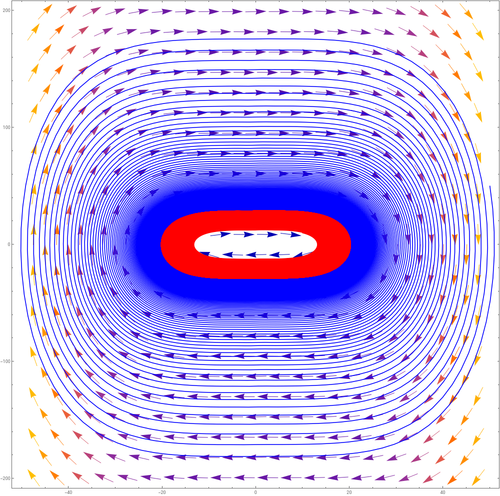
Here is again a rather contrived example from the above with equation:
f
x
x
cosx
10+
2
x
2
x
3
x
In[]:=
{x[t],y[t]}/.NDSolve[{y'[t]==-y[t]f[x[t]]-0.01,x'[t]==y[t],x[0]==#,y[0]==#},{x,y},{t,0,1000}][[1]]&/@{50,10};Show[VectorPlot[{y,-yf[x]-0.01},{x,-50,50},{y,-200,200},VectorPoints->20],ParametricPlot[%,{t,0,1000},PlotPoints->1000,PlotStyle->{Blue,Red}],ImageSize->1000]
3
x[t]
3
x
Out[]=
Where the blue trajectory is very slowly moving in towards the limit cycle and the red trajectory is very slowly moving out towards it.
The return of the Van der Pol oscillator
Remember the Van der Pol oscillator?
This actually gives you quite a bit of flexibility for families of vector fields which have unique stable limit cycles about the origin.
Lienard Systems were originally designed to model the radio and vacuum tube technology. Vacuum tubes were used originally instead of transistors in computers.
Exercise:
Come up with your own Lienard system, plot the vector field and try and find a trajectory numerically.