Coupled Pendulum System
Coupled Pendulum System
Modeling the motion of a system of multiple pendulums connected by springs
Introduction
Introduction
The purpose of the following text is to understand the process of modeling physical systems. More precisely the purpose is to model a system of coupled pendulums. The text is first going to explain the basic physical modeling and built on top of calculus and differential equation knowledge to develop a more complex system.
Physical properties of pendulums and springs
Physical properties of pendulums and springs
In this section the text is going to explain the concept of linear and constant kinematics, dynamics and the physical properties of pendulums and springs.
Understanding position, velocity and acceleration
Understanding position, velocity and acceleration
The position of an object is described by its location on space. The velocity of an object, on the other hand, can be explained by the the change of position in space with respect of time while the acceleration can be explained as the change of velocity with respect of time. It was Issac Newton, who does not need an introduction, that found out that the position, velocity and acceleration of an object can be also represented mathematically , more exactly as the derivatives and integrals of each other. This means that if one were to derivate the position one would get the velocity, and if one derivates the position twice one would get the acceleration. Moreover, by integrating the acceleration once, one will compute the velocity, and if one integrates acceleration twice, one will get the position of the same object. [x’’[ t ] = a[ t ], x’[ t ] = v[ t ], x[ t ] = x[ t ] ]
In the following diagram the position, velocity and acceleration is represented as integral and derivatives of each other respectively.
You can input different acceleration ranging from -3m/s^2 to 3m/s^2 ! !
In the following diagram the position, velocity and acceleration is represented as integral and derivatives of each other respectively.
You can input different acceleration ranging from -3m/s^2 to 3m/s^2 ! !
Out[106]=
◼
In this plot the horizontal axis is the time in seconds and the vertical axis is the distance in meters, velocity in meters per seconds and acceleration in meters per second square respectably.
Describing springs with Hook’s law to understand dynamics
Describing springs with Hook’s law to understand dynamics
It is important to remember that the dynamics of a system is the collection of forces acting on a system. These approach requires the three laws of Newton (inertia, action reaction pair and F=ma).The use of dynamics is interesting to scientist and physicist because it allows them to model with differential equations the motion of a system.
The string is a device that has the property of contracting and expanding depending on its displacement. The fifteen century physicist and chemist Robert Hook was one of the first scientist to formalize the behaviour of a spring. He noticed that, for instance, the force of the spring was proportional and in the opposite direction to the displacement. This is know as the Hook’s law. [F= k *x]
◼
For purposes of this text the focus is not going to be in deriving the differential equation; nevertheless, the knowledge of origin of this differential equation is going to be briefly described at the beginning of each section.
In[14]:=
Out[14]=
Out[123]=
◼
In the plot above the vertical axis is in Newtons and the horizontal axis is in centimeters.
Describing the energy of a spring
Describing the energy of a spring
The potential energy of an object attached to a spring can be model to the following equation. (Note that potential energy is energy that can be acuired) [u=k/2*x^2]
On the other hand, the kinetic energy of an object attached to a spring is model as most objects in motion.(Note that kinetic energy is the one of moving object) [k=m/2*v^2]
While the total energy of a system in a conservative system is just the sum of the potential and kinetic energy. (Note that the definition of energy is not totally defined) [E = u+k]
Out[124]=
◼
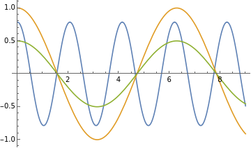
On the top plot the blue curve is the potential energy of a spring, the orange curve is the kinetic energy and the green line is the energy of the system . The horizontal axis represent the displacement on the x direction, meters, and the vertical axis is representing the energy in terms of Jules.
Understanding angular position, velocity and acceleration
Understanding angular position, velocity and acceleration
Just like linear motion, the rotational motion of an object is primarily described by the angle between a vector and an axis; thus the term of angular position, velocity, and acceleration.Moreover, the mathematical properties are the same as the ones for linear kinematics.[θ’’[ t ]= α [ t ], θ’[ t ] = ω[ t ], θ[ t ]=θ[ t ]]
Understanding pendulums dynamics
Understanding pendulums dynamics
The forces acting on a pendulum can be reduced to the following equation since only gravity can be said to be acting in such system.[F= m*l*ω^2 ]
Describing the energy of a pendulum
Describing the energy of a pendulum
The potential energy of a pendulum depends on the y displacement, assuming that the lowest point is the origin, and the kinetic energy is described by the common kinematic equation.[u=mgy] [k=m/2*v^2][E = u+k]
Simulating a single pendulum
Simulating a single pendulum
In this section the text is going to examine the development of a model for a pendulum.
Modeling with Newton method a single pendulum
Modeling with Newton method a single pendulum
By using the dynamics equations it is possible to model not only the forces interacting on a system but also to the motion of the object. The way to model such thing is to first reformulate the dynamics equation and afterwards switch acceleration and velocity to the derivative of position. The equation that is left is what scientist and engineers call a differential equation which has a unknown function as suppose of an unknown variable. From the dynamics equation we get the following differential equation for a single pendulum:
Dynamics
Differential Equation
Dynamics
Differential Equation
◼
Note that the process of setting up the dynamics equation can be better developed by using a free body diagram.
In[16]:=
g=10;l=1;
Out[71]=
[t]-10Sin[θ[t]],[0]0,θ[0]
′′
θ
′
θ
π
4
Solving the differential equations
Solving the differential equations
With the differential equation already set up, one will then solve the differential equation. Although a differential equation can be solved using analytical methods, but for practical purposes the differential equation is going to be solve using computational methods.
Out[109]=
θ
InterpolatingFunction
,ttModeling with different parameters
Modeling with different parameters
The following graph represents the sinusoidal function the angle between the pendulum and the positive x axis (see a diagram of a pendulum to make sense of it). Many of these curves have different initial conditions such as the initial velocity,initial position, initial length of the pendulum and gravitational acceleration. This plot also establishes the connection between the initial conditions and the motion of the object.
Out[110]=
◼
In the graph at the top the horizontal axis represents the time in seconds while the vertical axis represents the angle in radians.
Visualizing the single pendulum
Visualizing the single pendulum
In order to fully visualize the motion of a pendulum, the following animation shows the motion of a simple pendulum.
Out[112]=
Simulating two spherical masses connected by a spring
Simulating two spherical masses connected by a spring
In this section the text is going to develop the model for two balls connected by a spring over a frictionless surface.
Modeling with Newton method a spring connected to two masses
Modeling with Newton method a spring connected to two masses
Using the properties of a spring, the formulation of the dynamics of the system can set up. Moreover, just like the example of the pendulum the use of velocity and acceleration as the derivatives of position will bring rise of the differential equation that will model the motion of this spring system.
Solving the differential equation
Solving the differential equation
Once with the differential equation set up, the next step is to simply solve the differential equation. This step can be easily computed using multiple math and science software.
Modeling with different parameters
Modeling with different parameters
The first is the function is the shows the motion of the first ball.
The following function shows the motion of the second ball.
Visualizing the spring system
Visualizing the spring system
Displaying the 3D animation
Simulating two pendulums connected by a spring
Simulating two pendulums connected by a spring
Modeling with Lagrangian method three entangled pendulums in 3 dimensions
Modeling with Lagrangian method three entangled pendulums in 3 dimensions
Solving the differential equations system
Solving the differential equations system
With the equation set up, the system is solved using Dsolve command.
Modeling with different parameters
Modeling with different parameters
The following example is the function of pendulum one.
The following example is the function of pendulum one.
◼
The graph on top
The following example is the function of pendulum two.
Visualizing the pendulum system
Visualizing the pendulum system
Displaying the 3D animation
Further Explorations
Name of a related topic for exploration
Name of another related topics for exploration (repeat as needed)
Authorship information
Emilio Andres Vazquez
23 June 2017
emibars97@gmai.com

