Laplace Transform
Laplace Transform
The Laplace transform is particularly useful in solving linear ordinary differential equations such as those arising in the analysis of electronic circuits.
What is The Laplace Transform.
What is The Laplace Transform.
It is a method to solve Differential Equations.
The idea of using Laplace transforms to solve D.E.’s is quite human and simple: It saves time and effort to do so, and, as you will see, reduces the problem of a D.E. to solving a simple algebraic equation.
But first let us become familiar with the Laplace transform itself.
We now introduce a “prescription” how to create a new function called “F” out of the old function “f”. The interesting part will be that “F” will not depend on “t” anymore (as “f” does) but on an entirely new variable “s”.
You can say that we ,Laplace transform f from the t-space into F inside of the s-space.
The definition consists of two types of Laplace Transform they are,
Definition of a Bilateral Laplace Transform.
Definition of a Bilateral Laplace Transform.
A two-sided (doubly infinite) Laplace transform for an input function given as i[t] is defined as,
In[491]:=
Clear[s]input=f[t]*Exp[-st];Style[Integrate[input,{t,-Infinity,Infinity}],20]
Out[493]=
∞
∫
-∞
-st
Where s is a Complex Plain with real and imaginary axes.
Definition of a Unilateral Laplace Transform.
Definition of a Unilateral Laplace Transform.
A one-sided (singly infinite) Laplace transform for an input function given as i[t] is defined as,
In[494]:=
input=f[t]*Exp[-st];Style[Integrate[input,{t,0,Infinity}],20]
Out[495]=
∞
∫
0
-st
This is the most common variety of Laplace transform and it is what is usually meant by “the” Laplace transform. The unilateral Laplace transform L_t[f(t)](s) is implemented in the Wolfram Language as LaplaceTransform[function, t, s].
Generation of Laplace Transform for an input function.
Generation of Laplace Transform for an input function.
The Laplace transform is defined in the ‘ s ’ complex domain. Here we’ll take an input function w.r.t time (t) and try to obtain it’s Laplace Transform in the complex form. This can be done by the following steps and with the use of Fourier Transform.
Let’s take an Input function with respect to time into consideration.
◼
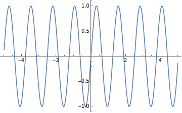
Plot an function as input data with respect to time. Here we take a Sin function w.r.t as an input.
In[394]:=
f[t_]:=Sin[5t]x=Plot[f[t],{t,-5,5}]
Out[395]=
Now According to the definition mentioned, we multiple different exponential function as ‘ s ’ where s is complex.
First we Multiply the Real part here that is where ‘ a ’ is a real number.
Here we take three different values of ‘ a ‘ into consideration.
First we Multiply the Real part here that is
-at
e
Here we take three different values of ‘ a ‘ into consideration.
◼
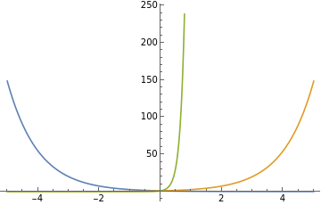
Plot different exponential functions as wheretistimeandaisarealnumber.
we take 3 different cases where a= -1,1,7.
-at
e
we take 3 different cases where a= -1,1,7.
In[474]:=
Plot[{E^-t,E^t,E^(7t)},{t,-5,5}]
Out[474]=
Now, we multiply the input function with the Real part of Exponential Function and get one step closer to achieving the fundamental definition of Laplace Transform.
◼
Make a table by multiplying different functions values of exponential ‘ a ‘ and plot their behaviour using TableForm.
In[108]:=
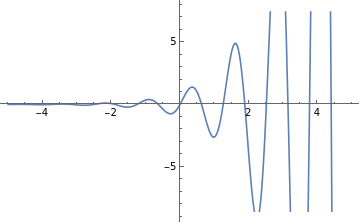
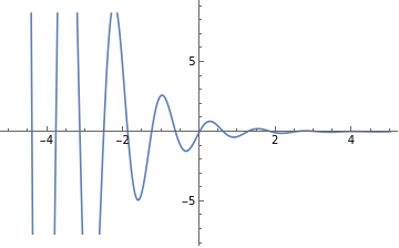
r[t_]:=f[t]*Exp[-at];TableForm[Table[{a,Plot[r[t],{t,-5,5}]},{a,{-1,1,7}}]]
Out[109]//TableForm=
-1 | |
1 | |
7 |
Here for each value of ‘ a ’ the graphical behaviour is shown with it.
Now we can achieve the Bilateral Laplace Transform by applying Fourier Transform to the System. But First,
What is Fourier Transform?
A Fourier transform (FT) converts a signal from the time domain (signal strength as a function of time) to the frequency domain (signal strength as a function of frequency).
Let’s take an Example into consideration.
Take an input function with respect to time.
Let’s take an Example into consideration.
Take an input function with respect to time.
◼
Create Input Data.
In[398]:=
fourierInput=Exp[-t^2]Sin[t]
Out[398]=
-
2
t
Now we take the Fourier Transform of the input and as per the definition see if the output is in the frequency domain.
◼
Apply Fourier Transform to the input function.
In[400]:=
FourierTransform[fourierInput,t,frq]
Out[400]=
(-1+Cosh[frq]+Sinh[frq])Cosh-Sinh
1
4
2
(1+frq)
1
4
2
(1+frq)
2
2
Here, the ‘ frq ‘ stands for the frequency. Let’s simplify to understand the equation better.
◼
Apply FullSimplify for better understanding.
In[402]:=
fourierOutput=FullSimplify
(-1+Cosh[frq]+Sinh[frq])Cosh-Sinh
1
4
2
(1+frq)
1
4
2
(1+frq)
2
2
Out[402]=
(-1+)
-
1
4
2
(1+frq)
frq
2
2
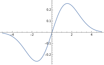
Now let’s plot the input and output functions for better graphical understanding in the range of -5 to 5.
◼
Apply Plot to the input for the time range.
In[403]:=
Plot[fourierInput,{t,-5,5}]
Out[403]=
◼
Apply Plot to the output for the frequency range for the imaginary part.
In[405]:=
Plot[Im[fourierOutput],{frq,-5,5}]
Out[405]=
Fourier Transform gives the frequency in an imaginary plane. Whereas, Laplace consists of both real and imaginary.
Thus to obtain the imaginary part of the complex domain of the Laplace transform definition, we apply Fourier Transform to the Function.
◼
Apply fourier to the real part and the output consist of a complex domain ‘ s ’.
For each value of ‘ a ‘ a different value of Laplace Transform is obtained, as we observe in the above equations. The Laplace Transform of the function is Complex is nature with ‘ a ‘ and ω. The obtained Laplace Transform is Bilateral or Two sided Laplace Transform.
The following is a demonstration of the Wolfram Language in-Built function LaplaceTransform.
Applying unilateral Laplace Transform to the initial input and examining the behaviour.
The Complex of the behaviour is substituted with the variable ‘ s ’ , where ‘ s ‘ consists of s = a + i ω ,and thus the input function in t domain is now Transformed in the s-domain.
◼
Plot the Laplace Transform in the s plane in 2D to see the behaviour.
Now, let’s see the behaviour in the complex plane with real and imaginary axes.
◼
Use Plot 3D to see the behaviour in the Complex Domain.
The interesting part will be that “F” will not depend on “t” anymore (as “f” does) but on an entirely new variable “s”.
You can directly use f(t) and F[s]
You can directly use f(t) and F[s]
Time v/s S (complex) Domain of Laplace Transform.
Let’s Examine the behaviour of the Laplace Transformation of a certain input
◼
Take Input function in time domain and see it’s nature in the s-domain, that is the complex domain.
Plot of the input function, the function taken here is Sin[3 t]+ Cos[4 t].
The above output is the Laplace transform represented as ‘ s ‘.
2D Plot of Laplace Transform with respect to ‘ s ‘.
This is the Laplace Transform of the input Function where ‘ s ‘ is displayed in it’s complex form.
The Laplace Transform of the input function is plotted on the s-plane with the real part and imaginary part of the plane are merged in a single 3D demonstration.
Laplace Transform v/s Fourier Transform.
Laplace Transform v/s Fourier Transform.
The main drawback of fourier transform (i.e. continuous F.T.) is that it can be defined only for stable systems. Where as, Laplace Transform can be defined for both stable and unstable systems.
Let’s Look at the fundamental expression of a fourier Transform and a Laplace Transform.
Let’s Look at the fundamental expression of a fourier Transform and a Laplace Transform.
◼
Use integrate and exponential.
The expression obtained the fundamental expression of a fourier transform where the input function is i[t].
Relation:
Relation:
The Laplace transform maps a function f(t) to a function F(s) of the complex variable s, where s=a+j ω.
Since the derivative f’(t)=d f[t] dt where f[t] is the input function, maps to sF(s), the Laplace transform of a linear differential equation is an algebraic equation. Thus, the Laplace transform is useful for, among other things, solving linear differential equations.
If we set the real part of the complex variable s to zero that is a=0 , the result is the Fourier transform F(j ω) which is essentially the frequency domain representation of f(t).
Thus using fourier transform the input function in the time domain is represented in the frequency domain.
The Basic example in which the real part of ‘ s ‘ that is ‘ a ‘ is zero is that the real part of the exponential in the definition of the Laplace transform is 1.
◼
Take a input function of Cos[4.3 t] and evaluate the Laplace of the imaginary plane.
This is the Laplace Transform of only the Imaginary part, that is the real part is zero. Thus this is equal the Fourier Transform of the same input function.
Graphical representation of the Laplace Transform from the range of -5 to 5.
History and Origin.
History and Origin.
The Laplace transform is named after mathematician and astronomer Pierre-Simon Laplace, who used a similar transform (now called the z-transform) in his work on probability theory.The current widespread use of the transform (mainly in engineering) came about during and soon after World War II although it had been used in the 19th century by Abel, Lerch, Heaviside, and Bromwich.
The early history of methods having some similarity to Laplace transform is as follows.
The early history of methods having some similarity to Laplace transform is as follows.
as solutions of differential equations but did not pursue the matter very far.
These types of integrals seem first to have attracted Laplace’s attention in 1782 where he was following in the spirit of Euler in using the integrals themselves as solutions of equations.However, in 1785, Laplace took the critical step forward when, rather than just looking for a solution in the form of an integral, he started to apply the transforms in the sense that was later to become popular.
He used an integral of the form,
He used an integral of the form,
Laplace also recognised that Joseph Fourier’s method of Fourier series for solving the diffusion equation could only apply to a limited region of space because those solutions were periodic. In 1809, Laplace applied his transform to find solutions that diffused indefinitely in space.
Applications.
Applications.
Circuit Equation.
Circuit Equation.
So, this Circuit Equation is to Solved and The current in the circuit is to be obtained. The Best way to approach this problem is through applying LaplaceTransform to the kirchhoff expression and then by taking back the inverse Laplace transform the current is obtained in the time domain.
The following is the equation of the circuit in differential form, by applying Laplace Transform we get the Algebraic form of the equation, which is the whole purpose of the transform.
The Power of Laplace Transform Converts this Equation into Algebraic equation in the Complex domain, ‘ s ‘ Plane.
◼
Solve the circuit equation in Mathematica by applying the LaplceTransform.
Thus the Differential equation is transformed into an normal Algebraic Equation.
Now let’s evaluate the value of the current ‘ i ‘ in the Laplace form.
◼
We obtain the answer by applying the function Solve.
Just the value of the current in the Laplace domain (complex domain ) is obtained quiet easily.
Let’s try to see the behaviour of current in the s- domain in the graphical representation.
Let’s try to see the behaviour of current in the s- domain in the graphical representation.
Let’s Plot the current in a 2D plane by keeping the value of ‘ s ‘ as real.
◼
Extract the value of ‘ i ‘ using part and then Ploting the function in the range of -5 to 5.
Now Let’s see the behaviour in the Complex plain by taking the s as a complex number.
◼
Define the complex behaviour of s and the Plot3D both real and imaginary part using Show.
Now we obtain the value of current back in the time domain using Inverse Laplace Transform function and thus the circuit is solved easily.
◼
Clear the value assigned to s and then obtain the inverse Laplace transform.
Further Explorations
Differential Equations.
Z- Transform
Region of Convergence
Fourier Series
Fourier Transform
Poles and Zeroes
Z- Transform
Region of Convergence
Fourier Series
Fourier Transform
Poles and Zeroes
Authorship information
Harish Chetty
23 June 2017
harishchetty1997@gmail.com
