Differential Drive (Path Following).
By: Santiago Sánchez V.
Import["https://www.cse.unr.edu/robotics/tc-apc/sites/cse.unr.edu.robotics.tc-apc/files/differenticalfigure.png"]
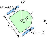
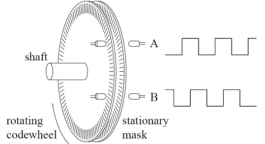
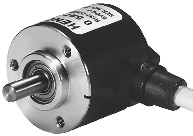
Differential Drive is one of the configurations for robot mobility, in consist on 2 driven wheels on each side of the robot and maybe some free wheels for stability, Each of the driven wheels has encoders which are able to count the revolutions in terms of angles or derived to speed with simple geometric equations.
Column[{Import["http://hades.mech.northwestern.edu/images/2/22/Encoder_diagram.png"],Import["http://img.directindustry.com/images_di/photo-g/5789-2409187.jpg"]}]
ConversionFactor
The first task is to convert the pulses of the encoder into a linear displacement, this can be done by the following equation, this equation give us a result of a factor that we’ll call f.
f[d_,N_]:=
d*π
N
Where,
d = Diameter of the wheel.
N = Number of pulses.
Set up your own specifications.
d = Diameter of the wheel.
N = Number of pulses.
Set up your own specifications.
F=Manipulate[N[Table[f[Diameter,NumPulses],1]],{Diameter,1,40,1,Menu},{NumPulses,1,200,1,Menu}]
LinearVelocity
The linear velocity of the robot is calculated by the following equation.
Vlin[Vr_,Vl_,F_]:=*F
Vr+Vl
2
You can change the linear velocity of your robot by setting the next parameters.
Vl=Manipulate[Table[Vlin[Vright,Vleft,F],1],{Vright,1,20,1},{Vleft,1,20},{F,0,10,0.0001,Menu}]
Angular Velocity
Angular Velocity
Instead of driving each wheel separately, you can get the angular velocity to make sure the robot is turning at the desired speed with the next equation.
W[Vr_,Vl_,F_,l_]:=*F
Vr-Vl
l
You could set up the angular velocity by setting Vr,Vl, F, L; where L is the distance between the 2 wheels.
Wf=Manipulate[Table[W[Vright,Vleft,F,L],1],{Vright,1,100,1},{Vleft,1,100},{F,0,10,0.0001,Menu},{L,1,30,1,Menu}]
You could mix all of the last equations in just one chart due to they are related to each other
Vlin[d_,n_,Vr_,Vl_]:=*;W[d_,n_,Vr_,Vl_,l_]:=*;
Vr+Vl
2
d*π
n
Vr-Vl
l
d*π
n
VW=Manipulate[N[Table[List[Vlin[d,n,Vr,Vl],W[d,n,Vr,Vl,l]],1]],{Vr,1,100,1},{n,1,1000,1,Menu},{Vl,1,100},{d,1,20,0.1,Menu},{l,1,30,1,Menu}]
CurrentPosition
Having interacting with every piece of the formulas, now it’s time to join them all to be able to know if our model works.
Knowing the approximate values of linear an angular velocity, press start and move the sliders to be able to see how the robot is able to navigate across the environment.
ClearAll[x,y,θ,w,v]x=y=θ=w=v=0;task=CreateScheduledTask[θ=θ+w;x=x+vCos[θ];y=y+vSin[θ];];
Panel@Column[{Grid[{{"Angular Velocity",Spacer[10],Slider[Dynamic[w],{-0.6,0.6},Appearance"Labeled"]},{Dynamic[y],Spacer[10],Slider[Dynamic[v],{0,10},Appearance"Labeled"]}}],List[Dynamic[Graphics[{Arrow[{{x,y},{x+vCos[θ],y+vSin[θ]}}],Red,Circle[{0,0},3]},FrameTrue,BackgroundGray[0.1],PlotRange{{x-50,x+50},{y-50,y+50}}]],Column[{Button["Start",StartScheduledTask[task]],Button["Stop",StopScheduledTask[task]],Button["Reset",x=y=w=θ=v=0]}]]}]
Now Theta desired is the Setpoint for the PID controller, and is subtracted the current Theta generating the error e(t) for the controller.