Segmentation using Mathematical Morphology
There are multiple ways to do segmentation, mathematical morphology is a geometric approach for extracting image components that are useful in the representation and description of region shape. In this exploration, we illustrate several basic concepts in mathematical morphology, such as erosion, dilation, opening, and closing. And we will examine how to apply those simple operators to perform segmentation on medical images.
Introduction of Segmentation
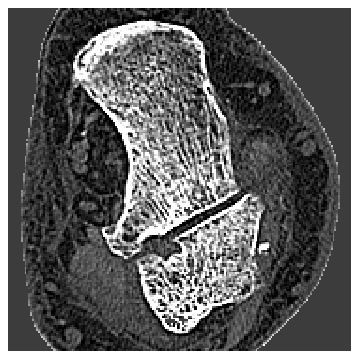
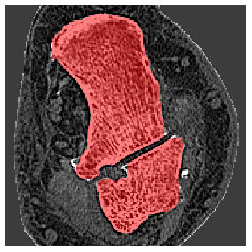
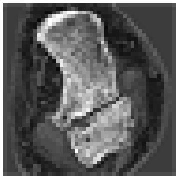
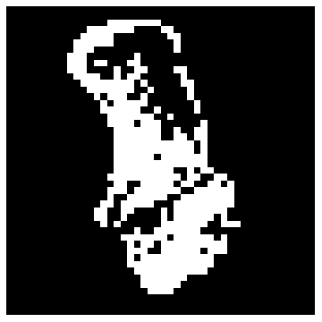
Our task is separating object from background in a grayscale picture. Here is an example:
Helper functions
Helper functions
Connected Components
Definition: A maximum set of pixels (voxels) in the object or background, such that any two pixels (voxels) in the set are connected by a path of connected pixels (voxels).
Connectivity (2D)
Connectivity (2D)
Two pixels are connected if their squares share:
◼
A common edge
◼
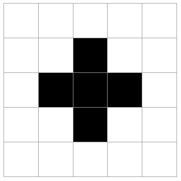
4-connectivity
Out[23]=
◼
A common vertex
◼
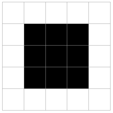
8-connectivity
Out[24]=
Therefore, based one two types of connectivity, we can have two kinds of operating structure elements:
In[25]:=
structCross={{0,1},{0,-1},{1,0},{-1,0}};structSquare={{-1,-1},{-1,0},{-1,1},{0,1},{1,1},{1,0},{1,-1},{0,-1}};
Finding Connected Components
The “flooding” algorithm
Start from a seed pixel / voxel, expand the connected component.
Either do depth-first or breadth-first search (a LIFO stack or FIFO queue)
1. Initialize 1. Create a result set S that contains only P. 2. Create a visited flag at each pixel, and set it to be false except for P. 3. Initialize a queue (or stack) Q that contains only P.2. Repeat until Q is empty: 1. Pop a pixel x from Q. 2. For each unvisited object pixel y connected to x, add y to S, set its flag to be visited, and push y to Q.3. Output S.
In[27]:=
flood[imageData_,givenPixel_,connectivityType_]:=Module {x,y,w,h,struct,center,queue,neighbors,newQueue,newPixels}, struct=Switch[connectivityType,0,structSquare,1,structCross]; {w,h}=Dimensions[imageData]; newPixels=Table[0,w,h]; queue={givenPixel}; newPixelsgivenPixel1,givenPixel2=1; Whilequeue≠{}, center=First@queue; newQueue=Rest[queue]; queue=newQueue; neighbors=(center+#)&/@struct; ScanIf1≤#1≤w&&1≤#2≤h&&imageData#1,#21 &&newPixels#1,#20, AppendTo[queue,{#〚1〛,#〚2〛}]; newPixels#1,#2=1&,neighbors; ; newPixels
Example
Example
Let’s start from a small dataset - a low resolution CT scan of human foot bone.
In[28]:=
boneSmall=PNGtoGray["bone_small.png"];showGrayImage[boneSmall]
Out[29]=
In[30]:=
binBoneSmall=getBinarizedImage[boneSmall,.5];showBinaryImage[binBoneSmall]
Out[31]=
Loop through each pixel, if it’s not labeled, use it as a seed to find a connected component, then label all pixels (voxels) in the component.
By 8-connectivity, we have one component, while by 4-connectivity, we have 2 components.
Mathematical Morphology
Structure element B is symmetric if
Morphology Operators
Morphology operators can perform operations to change shapes
◼
Erosion
Erosion of a binary image with a disk - shaped structuring element :
◼
Dilation
Dilation of a binary image with a disk - shaped structuring element :
Duality (for symmetric structure elements)
Erosion:
Dilation:
Opening: erode, then dilate
Closing: dilate, then erode
Complement of union of all B that can fit in the complement of A
After erosion
After dilation
Example
Example
Bone Segmentation
Bone Segmentation
Human foot CT image
Human foot CT image
Here we will apply this algorithm on a full-resolution CT image of a human foot.
The first step is to binarize it.
Here by observing, we find:
1. Islands (holes) of the object are holes (islands) of the background
2. Islands (holes) are not as well-connected as the object (background).
1. Islands (holes) of the object are holes (islands) of the background
2. Islands (holes) are not as well-connected as the object (background).
Take the largest 2 connected components of the object
Then we invert the largest connected component of the background
The morphology operators are used to smoothing out object boundary.
Here we get a segmentation of the bone!
Other Segmentation
Other Segmentation
If we wrap this process up, we can do segmentation in general to many cases :
Mouse brain segmentation
Breast Lesion
Breast Lesion
Further Explorations
Authorship information
06/23/2017
zhu_wenzhen@icloud.com